
For those of you who export charging products to the EU, you have most likely heard of the EN 55032 standard. Many people’s first reaction is: Does my charger have to pass this? Do all charging adapters need to be tested? In fact, there is a core premise here: not all charging products are subject to EN 55032, and the first step must be to conduct a product classification determination. Today, we will thoroughly explain the relationship between this standard and charging products from beginner to advanced levels, to help you avoid common pitfalls.
First, Understand: What Exactly Does EN 55032 Regulate?
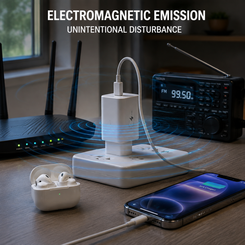
To understand this standard, we must start with “electromagnetic noise”: when you plug a fast charging adapter into a socket, the nearby radio makes a hissing sound, or Bluetooth earphones occasionally disconnect, it is most likely caused by interference from unintentional electromagnetic signals leaked during the operation of the charger; such signals are also called electromagnetic disturbances. EN 55032 is an electromagnetic disturbance emission standard specifically formulated by the EU for multimedia equipment (MME), belonging to the “emission” branch of the electromagnetic compatibility (EMC) field — in simple terms, it regulates “your product not disturbing others”, and does not regulate “whether your product can withstand interference from others”.
What is Its Legal Status?
Many people confuse standards with laws. In fact, EN 55032 itself is not a law; it is one of the harmonized standards under the EU EMC Directive: the specific version of EN 55032 cited in the Official Journal of the European Union (OJEU), when correctly applied and its requirements are met, can provide a presumption of conformity for the relevant essential requirements of the EMC Directive. Manufacturers still need to complete applicability judgment, conformity assessment, and technical documentation preparation. The citation, withdrawal, and transition dates of that specific version in the OJEU shall prevail.
In addition, special attention should be paid: there is no such thing as a separate “EN 55032 certification”. It is only a test standard, and the corresponding test report is one of the technical supporting documents for signing the EU Declaration of Conformity (EU DoC), not a separate certificate.
Why Should Charging Products Pay Special Attention?
Charging products happen to be a category with high incidence of electromagnetic noise: the high-frequency on-off of switching power supplies and the switching of fast charging protocols are common sources of electromagnetic noise. If a product falls within the scope of EN 55032 but does not meet the requirements, it cannot be legally sold in the EU at all. Charging accessories with fast charging or intelligent control functions usually have more switching and protocol operating states, which may increase the complexity of electromagnetic disturbance assessment, but their actual disturbance level still needs to be confirmed through testing combined with circuit design, filtering, layout, cables, and operating modes, and should be assessed in advance.
Core Prerequisites for Applicability
The first pitfall many people fall into is assuming that all chargers are subject to EN 55032. In fact, its scope of application is very clear:
- It only applies to multimedia equipment (MME) and eligible supporting power supplies/accessories; not all charging products can be directly covered by it;
- To determine whether a charging product is “multimedia-related”, the core is to check whether it has multimedia functions such as data transmission, audio and video processing, and intelligent interaction. Having a data interface is only one of the clues and cannot be used for direct determination;
- It should also be judged in combination with product attributes: whether it is sold independently or as a supporting product, whether it is a component of multimedia equipment, and whether there is a corresponding dedicated product standard (if there is a dedicated emission standard, the dedicated standard shall be used first);
- If the product has wireless functions such as Bluetooth and Wi-Fi, it must additionally comply with the RED Directive. EN 55032 only covers unintentional electromagnetic noise and does not regulate intentional radio emissions.
Several Easily Confused Concepts
People who are new to this field can easily confuse different standards. Let’s clarify the boundaries first:
- Difference from EN 55035: For equipment belonging to MME, EN 55032 is usually used for emission, and EN 55035 for immunity; for other products, emission and immunity assessments shall be conducted in accordance with applicable product-specific or general EMC standards. Passing EN 55032 does not mean full EMC compliance;
- Difference from electrical safety standards: EMC regulates electromagnetic interference risks, while safety standards regulate risks such as electric shock and fire. They belong to completely different compliance dimensions and cannot replace each other;
- Passing EN 55032 ≠ full CE compliance: CE compliance involves multiple requirements such as EMC, safety, radio, and RoHS. EN 55032 is only one of the standards for the EMC emission part.
How to Determine Whether Your Charging Product Is Applicable
Since not all charging products are applicable, how should we specifically determine it? We can sort it out step by step logically, without guessing.
Core Determination Logic
You can think of it as a step-by-step elimination process:
- First, clarify the functions and attributes of the product, as well as whether it is sold independently, sold with a complete multimedia unit, or only used as an accessory;
- Determine whether it is multimedia equipment, or a supporting power supply/accessory for multimedia equipment, with the core being the intended use and supporting relationship;
- Confirm whether there is a corresponding dedicated emission standard. If yes, use the dedicated standard first; if not, then consider EN 55032;
- If it is confirmed to be applicable, then determine whether it is Class A or Class B;
- Finally, check the status of the standard version cited by the OJEU in the target market to confirm that the test version has compliance validity;
- If you are unsure, be sure to consult a qualified testing institution or regulatory expert, and do not judge based on feeling.
Applicability Differences for Different Supply Forms
For the same charger, different sales forms may have different applicability rules:
- Independently sold chargers/adapters: the product attributes need to be determined separately, and those that meet the requirements need to be tested separately;
- Adapters provided with the complete multimedia unit: shall be evaluated in accordance with the actual or representative system configuration specified by the manufacturer. They can be tested in the complete unit configuration, or evaluated separately based on their independent functions and applicable standards, but separate test results cannot automatically replace the emission assessment of the complete unit configuration;
- Passive charging cables used only as accessories: have no active emission sources, and do not need to be separately subject to EN 55032. However, if it is an active intelligent charging cable with a chip, it needs to be determined separately.
Applicability Reference for Common Charging Products
We have compiled the general situation of several types of common charging products for your quick comparison, but the final determination must be combined with actual functions:
- Requires further assessment: USB/USB-C chargers with data interfaces, active intelligent charging cables, docking stations/power strips with data functions;
- Usually not tested separately: purely passive charging cables, purely conductive plug/charging port metal parts (these are generally tested together with the complete unit);
- Requires item-by-item determination: power banks need to be comprehensively judged in combination with functions, ports, intended use, and target market regulations;
- Usually not directly applicable: independent wall-mounted chargers that only supply power and have no multimedia functions are generally not within the scope of EN 55032, but it is still necessary to sequentially check applicable product-specific, product-family, or general EMC standards based on product use, structure, and target market, and assess emission, immunity, and applicable power quality requirements.
How to Classify Class A/B Levels
After confirming that EN 55032 is applicable, you also need to select the correct test level. Many people mistakenly think that the level is related to power, but in fact it is not at all.
| Comparison Dimension | Class B (Residential Grade) | Class A (Industrial/Commercial Grade) |
|---|---|---|
| Applicable Scenarios | Intended for use in residential environments | Equipment not intended for residential environments |
| Strictness of Limits | Stricter | Relatively lenient |
| Core Basis for Determination | Intended use, sales target, instructions for use, reasonably foreseeable household scenarios | Intended environment, conditions of use, and product positioning specified by the manufacturer |
| Relationship with Power | No direct relationship | No direct relationship |
When determining the level, it shall be judged based on the intended environment, instructions for use, sales positioning, and reasonably foreseeable use specified by the manufacturer. Class B applies to equipment intended for use in residential environments, and Class A applies to equipment not intended for residential environments. If the equipment may be used in a residential environment, it is also necessary to check the warnings and conditions of use applicable to Class A equipment, and the Class B requirements cannot be evaded solely by the “industrial grade” label.
Evidence to Be Retained for Applicability Confirmation
After completing the classification determination, it is best to retain relevant documents to avoid being unable to explain clearly during subsequent compliance inspections: on the product side, retain specifications, port function descriptions, principle block diagrams, bill of materials (BOM), and firmware version descriptions; on the marketing side, retain user manuals, sales page positioning, and descriptions of target markets and sales targets; on the compliance side, retain product classification risk assessment records. If it is a supporting accessory, also retain the compliance certificate of the supporting complete unit.
What Exactly Is Tested: Conducted and Radiated Emissions
The core test items of EN 55032 mainly correspond to different propagation paths of electromagnetic noise. We can quickly distinguish them with a table:
| Type | Propagation Path | Common Test Frequency Band | Common Problems in Charging Products |
|---|---|---|---|
| Conducted Emission | Propagates along cables such as power cords and charging cables | 150kHz~30MHz (subject to the standard version) | Insufficient internal filtering, excessive common-mode current on input and output lines |
| Space Radiated and Applicable Magnetic Field Emission | Propagates to space or near field | The frequency band and measurement items are determined according to the specific version of EN 55032, equipment type, and test conditions, and cannot be uniformly assumed to start from 30MHz | Chaotic internal layout, insufficient cable/enclosure shielding, structural gap coupling |
Conducted Emission Test
The logic of the conducted emission test is very simple: it measures the electromagnetic noise conducted outward by the product through different ports. For example, the test at the AC power supply end generally uses a Line Impedance Stabilization Network (LISN) — a device specifically designed to isolate the noise of the power grid itself and ensure test accuracy.
For charging products, the most common cause of excessive conducted emission is insufficient design of the internal filter circuit, or excessive common-mode current on the input and output lines, which will be discussed in detail later when we talk about rectification.
Radiated Emission Test
The radiated emission test measures the unintentional radio frequency electromagnetic noise emitted by the product through the air. The test environment generally uses a semi-anechoic chamber (a special room with walls covered with wave-absorbing materials to avoid signal reflection interfering with the results), and an accredited open area test site or alternative site can also be used.
Pay attention to its test boundaries: the emission items of EN 55032 usually include conducted disturbances at the AC power supply end and wired network end, as well as space radiated or magnetic field emissions in specified frequency bands. Whether it is necessary to perform magnetic field emission measurements below 30MHz, the measurement frequency band and upper limit shall be determined according to the applicable version, equipment size/type, and standard clauses, and cannot be uniformly assumed to start from 30MHz or exclude all low-frequency magnetic fields.
Test Process and Detector Rules
Many people don’t know that the test does not produce results after a single direct test, but has a fixed process: first perform a peak pre-scan to quickly locate frequency points with high noise, and then use the detector specified in the standard for the final compliance test.
There are two commonly used detectors: quasi-peak is used to simulate the human perception of interference from pulse noise (for example, for intermittent noise, quasi-peak can better reflect the actual degree of interference), and average is used to measure the intensity of continuous noise. Special attention should be paid: peak pre-scan is only used to locate problems and cannot be used as the final basis for conformity determination.
In addition, the layout requirements during testing are very strict: test distance, site type, placement of the product under test, length and routing of cables must all strictly comply with the standard, otherwise the results have no reference value.
Testing Must Be Close to the Actual Sales Configuration
This is a pitfall that many small manufacturers easily fall into: in order to pass the test, they use test cables or accessories that cannot represent the actual use situation, or only test the no-load mode. Such reports are insufficiently representative.
The test configuration shall be based on the actual or representative sales configuration specified by the manufacturer, using cables, accessories, and termination methods that can represent the product’s use situation and are confirmed by the test plan. If the actually sold cables, plugs, or accessories will change the disturbance results, they shall be included in the representative or worst-case configuration assessment, instead of being arbitrarily replaced by unrepresentative test accessories. If subsequent replacement of accompanying accessories may change the disturbance results, conformity also needs to be re-evaluated. Although passive charging cables do not need to be tested separately, they will directly affect the test results of supporting products and cannot be replaced casually.
The operating modes shall also cover representative and worst-case states determined by the manufacturer and the laboratory based on risk analysis, including standby, normal charging, fast charging, protocol switching, and simultaneous operation of multiple ports when necessary. Here we need to correct a common misconception: the worst-case operating condition is not the default full load or fast charging mode, which must be confirmed through engineering analysis or pre-scan. Some products have higher noise during protocol switching or light load.
The input voltage is not fixed at 230V/50Hz either. Representative or worst-case conditions shall be selected according to the product’s rated voltage/frequency range. For example, wide-voltage products may have higher noise at 110V, so they need to be tested at 110V.
Why Test Results May Vary for the Same Product
Many people encounter the situation that “the same sample has different test results in two laboratories”. In fact, there are many variables that affect the test results, which are mainly divided into four categories:
Product’s Own State
Different operating modes, load sizes, and port combinations (for example, a multi-port charger charging two devices at the same time vs. charging one device) have different disturbance levels; different firmware versions have differences in fast charging control strategies and chip operating timing, which may also change the noise level; there are also batch differences in structure and materials, such as fluctuations in filter component selection, circuit layout, and shielding process, which may lead to changes in results.
Test Configuration and Environment
The length, shielding performance, and placement of the charging cable, as well as the specifications of accompanying accessories, will directly affect the test results; wide-voltage products may have varying disturbance levels under different input voltages and frequencies; the site type of the radiated test, product orientation, distance from the antenna, and surrounding reference objects will all affect the values.
Standard Version and Level
Under the same conditions, the limits of Class B are usually stricter than those of Class A, but the specific difference depends on the frequency band, detector, and port, and there is no unified value; different versions of standards, amendments, and versions adopted by different countries may have adjustments in frequency bands, port definitions, and limits; the standard version used in the test report must match the product launch time and target market requirements, otherwise its compliance validity cannot be judged solely by the version name.
Measurement Error and Critical Determination
Test equipment calibration, site attenuation, and personnel operation will all bring small numerical errors, which is a normal phenomenon. If the measured value is very close to the limit, it is a high-risk situation and requires comprehensive assessment combined with the laboratory’s determination rules and measurement uncertainty, but ordinary users do not need to calculate it themselves — you cannot directly add or subtract uncertainty from the limit as a general conformity criterion. Everything shall be subject to the formal report conclusion made by a qualified laboratory in accordance with applicable rules.
How to Read an EN 55032 Test Report
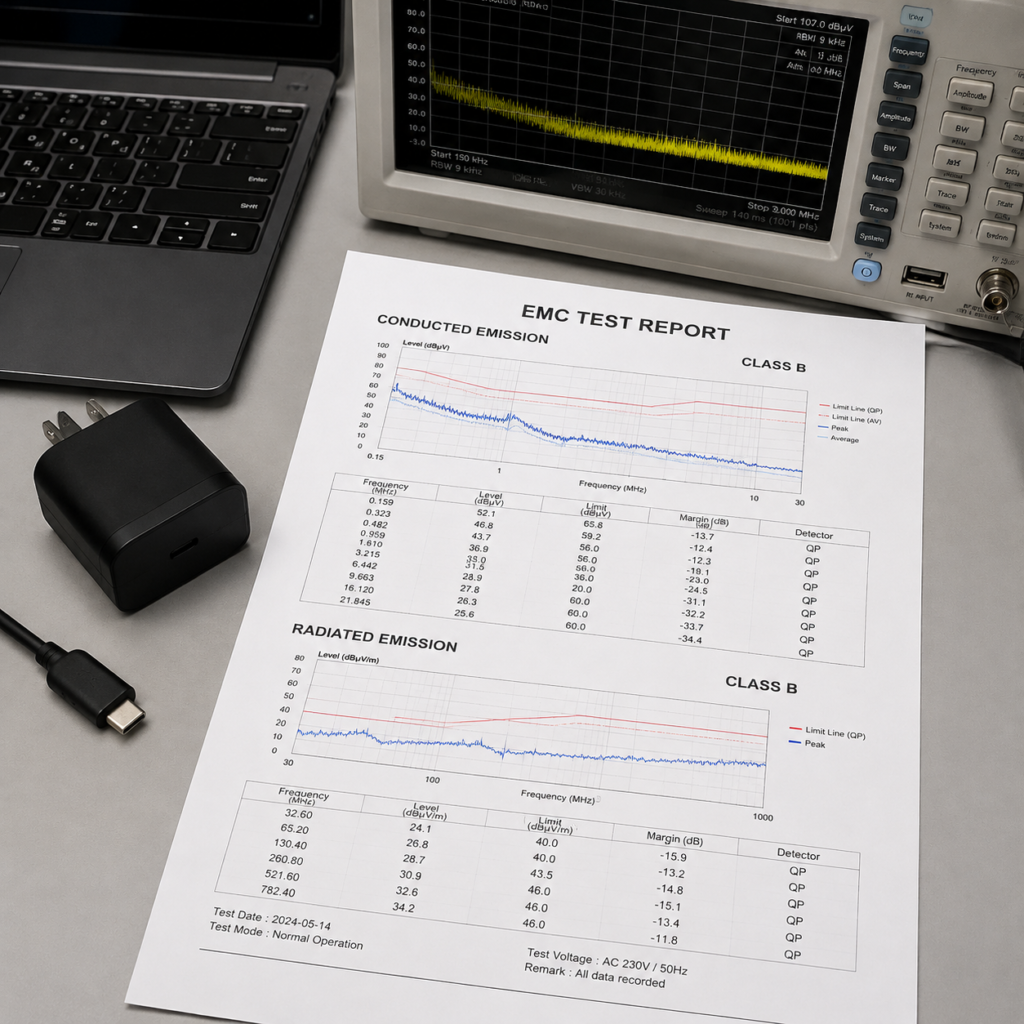
When you get a test report, you don’t have to be intimidated by the dense charts. From beginner to advanced, you can quickly judge using these methods.
Beginner: 3 Steps to Check Basic Conformity
For those who are new to this, first grasp three core points, and you can eliminate most obviously problematic reports:
- Check basic information: product model, test level (Class A/B), standard version number, and whether this version is cited by the OJEU, and whether it matches your product positioning;
- Confirm test coverage: whether both conducted and radiated items are tested, whether applicable ports are covered, and whether typical operating modes (such as fast charging, multi-port operation) are all included;
- Check the final conclusion: the formal conclusion shall be made based on the limits of applicable standards, detectors, test configurations, and laboratory conformity determination rules, and cannot be concluded solely based on a certain spectrum diagram or a certain pre-scan peak.
Intermediate: Identify 3 Types of High-Risk Reports
After having certain experience, you also need to be able to identify high-risk reports that look qualified but may actually not be recognized:
- Only test no-load/light load: does not cover representative operating modes that may produce the maximum disturbance, such as not testing fast charging or simultaneous operation of multiple ports. Such reports have very low reference value;
- Household products tested according to Class A: if the product is intended for use in a residential environment but is not assessed according to the corresponding Class B requirements, or does not meet the warnings and conditions of use applicable to Class A equipment, the report has a high compliance risk;
- Use unrepresentative test accessories: the charging cables, plugs, or other accessories used during testing are inconsistent with the actual sales configuration, which may cause the results to not represent the actually sold products.
Of course, the recognition of the report shall be combined with the scope of application, test plan, manufacturer’s declaration, and laboratory determination. There is no absolute definition of “invalid”, but the risks of these three types of situations are very high, and you must avoid them.
How to Read the Limit Table
When reading the limit table, you must match the five dimensions of port type, test distance, frequency band, detector, and Class level at the same time. You cannot apply it casually if any one is missing. For example, the limit for radiated emission at a distance of 3 meters cannot be applied to a test at a distance of 10 meters; the limit of Class A cannot be used to judge Class B products.
Commonly used units are also easy to remember: conducted emission uses dBμV, radiated emission uses dBμV/m. The larger the value, the stronger the noise. There is also a practical concept called “margin”, which is the limit minus the measured value. The larger the margin, the safer the product, and it is not easy to exceed the limit even if there are batch fluctuations. Limit tables for different ports and different test distances are independent and must never be mixed.
How to Read the Core Content of the Report
The spectrum diagram in the report is actually very simple: the horizontal axis is frequency, the vertical axis is noise intensity, and the straight line above is the limit line. Peaks exceeding the limit line may be risk points that need to be further confirmed according to the final detector and conformity determination rules. You cannot directly equate any peak on the pre-scan diagram with formal non-conformity.
Configuration fields should be checked emphatically: test site, measurement distance, input conditions, cable configuration, detector type, whether they meet the standard requirements and the actual situation of your product.
As for “measurement uncertainty”, it represents the uncertainty related to the measurement result. Whether to include it in the conformity determination and what determination rules to adopt shall be implemented in accordance with applicable standards, laboratory procedures, and relevant regulatory requirements. Readers cannot simply add or subtract uncertainty from the limit by themselves.
Additional Checkpoints for Charging Product Reports
For charging products, three more details need to be checked:
- Accessory check: whether the test plan considers accompanying accessories such as charging cables and plugs that will affect the disturbance results. For example, if you sell a charger with two different cables, you need to confirm whether the representative or worst-case configuration is covered;
- Mode check: shall cover representative and worst-case operating modes determined by the manufacturer and the laboratory based on risk analysis, including fast charging, simultaneous operation of multiple ports, and protocol switching states when necessary. It is not a given that all nominal power modes are tested one by one;
- Boundary check: for products with wireless functions, whether there is a distinction between unintentional emissions of EN 55032 and intentional emissions of radio standards. Do not treat normal Bluetooth and Wi-Fi signals as unintentional disturbances targeted by EN 55032.
Relationship of the Compliance Evidence Chain
Finally, remember: the EN 55032 test report is only one of the supporting documents for EMC compliance, not the entirety of CE compliance. Technical documents shall include materials that can prove compliance with applicable regulations and standards, including design descriptions, applicability analysis, test reports, and necessary risk/conformity assessment records; specific documents shall be determined according to applicable directives and product conditions. Before signing the EU DoC, conformity assessments of all applicable regulations shall also be completed.
Complete compliance materials may also include compliance documents for other applicable standards, such as safety, radio, RoHS, etc. The EN 55032 test report does not automatically cover the complete unit, all ports, all modes, or other applicable directives.
What to Do If Exceeding the Limit: Troubleshooting and Rectification Ideas
If the test fails, don’t panic. Electromagnetic disturbance problems can basically be solved through rectification. The key is to proceed step by step according to the closed-loop logic, and do not modify blindly.
Overall Rectification Logic (Closed-Loop Verification)
- First eliminate setting errors: confirm whether the test configuration and operating mode meet the requirements, for example, whether a charging cable that can represent the actual use situation is used, and whether modes that may produce large disturbances are covered. Many “exceeding limits” actually require checking the test settings first;
- Locate the disturbance path: first figure out whether it is conducted excess or radiated excess, whether it is a problem with the input port, output port, or space coupling;
- Targeted rectification + verification: modify after finding the problem, and use A/B replacement (for example, replace a common-mode inductor and compare the results before and after) and retesting to verify the effect after modification, to ensure that the rectification is effective.
Troubleshooting Directions for Excessive Conducted Emission
If the conducted emission exceeds the limit, first check from the following directions:
- Filter components: insufficient selection of common-mode inductors, X/Y capacitors, etc., or unreasonable layout, which do not play a filtering role;
- Common-mode path: abnormal common-mode current caused by input circuit, Y capacitor circuit, common-mode filter, transformer parasitic capacitance, or enclosure structure;
- Output port: insufficient filtering of the DC/USB output port, or excessive common-mode current of the charging cable.
Special reminder here: do not blindly add grounding measures, especially for Class II appliances (that is, household charging adapters that have no grounding pin and rely on double insulation to ensure safety). It is necessary to distinguish between protective grounding, functional grounding, and floating ground design. Randomly adding grounding will instead bring safety risks.
Troubleshooting Directions for Excessive Radiated Emission
If the radiated emission exceeds the limit, focus on checking these types of causes:
- Internal layout: the loop area of high-speed current is too large, and the circuit layout is chaotic, leading to parasitic coupling;
- Structural shielding: the enclosure gap is too large, the connection of the metal shell/shielding layer is poor, and the shielding process is insufficient;
- Cable radiation: the common-mode current of the charging cable is too large, the shielding connection is poor, or the cable placement is unreasonable.
We also need to correct a misconception: not all charging cables need shielding. Whether to shield or not shall be comprehensively judged in combination with port design, common-mode path, and safety requirements. Blindly adding shielding may be useless and will increase costs.
These Issues Are Not Regulated by EN 55032
Pay attention to the boundaries during troubleshooting: intentional emissions of radio equipment shall be assessed in accordance with RED and applicable radio standards; emissions generated by low-frequency magnetic fields and wireless charging shall be confirmed according to equipment type, frequency band, and applicable standards. EN 55032 cannot be uniformly excluded solely based on “low frequency” or “wireless charging”, and other product-specific EMC or wireless standards may also need to be assessed.
Beginner-Level Preliminary Screening Method (Only as Engineering Clues)
If there are no laboratory conditions, you can also use several simple methods for preliminary troubleshooting, but note: these can only be used as engineering clues and absolutely cannot replace formal standard tests:
- Phenomenon observation: place the charger close to a radio or Bluetooth earphones to see if there is hissing sound or disconnection, which can initially determine whether there is obvious interference;
- Simple replacement test: replace the charging cable, shorten the cable length, adjust the product placement, and observe whether the interference is reduced, which can assist in locating the disturbance path;
- Preliminary compliance check: if the formal test exceeds the limit, first confirm whether accessories that can represent the actual use situation are used, and whether typical or operating modes that may produce large disturbances are covered, to eliminate low-level errors first.
Full Compliance Process and Common Misconceptions
Compliance Process from Design to Launch
EN 55032 compliance is not about testing after the product is made, but should run through the entire product cycle:
- Early stage: first conduct product classification, confirm applicable standards and levels, and conduct EMC risk assessment in advance to avoid major modifications in the later stage;
- Middle stage: after mold opening and prototyping, first conduct engineering pre-scan, rectify problems in time, verify and optimize, and do not wait until formal testing to find problems;
- Late stage: after rectification is completed, conduct formal testing, sort out a full set of technical documents, complete conformity assessments of all applicable regulations, and sign the EU DoC before launching;
- After-sales: if there are changes in subsequent models, firmware, or accompanying accessories, conformity shall be re-evaluated to ensure that mass-produced products are consistent with test samples.
6 Most Common Pitfalls for Beginners
We have compiled the most common cognitive misconceptions for beginners to help you avoid detours:
- Misconception 1: All chargers need to be tested for EN 55032 — only multimedia equipment or its supporting equipment is applicable. Pure power supply products correspond to other standards;
- Misconception 2: Passing EN 55032 means full EMC compliance — EMC includes two parts: emission and immunity, and it is also necessary to pass the corresponding immunity standard (such as EN 55035);
- Misconception 3: Low-power charging adapters will definitely pass — whether it exceeds the limit is related to design, has no direct relationship with power, and the Class level is also unrelated to power;
- Misconception 4: Radiated emission is fixedly tested at 30MHz~6GHz — the specific items, frequency bands, and upper limits of space radiated and magnetic field emissions are determined according to the standard version, equipment type, and test conditions, and cannot be fixedly summarized as 30MHz~6GHz;
- Misconception 5: EN 55032 report equals CE certification — the report is only a supporting document. It is necessary to complete the conformity assessment and sign the DoC in combination with other requirements to complete CE compliance;
- Misconception 6: Chargers with data interfaces must be subject to this standard — data interfaces are only classification clues, and comprehensive determination is required in combination with functions and intended use.
Relevant Standards and Applicability Boundaries
Finally, let’s clarify the relationship between several relevant standards to avoid confusion:
- With CISPR 32: CISPR 32 is an IEC international standard, and EN 55032 is the European adopted version. Only when a specific version of EN 55032 is listed as a harmonized standard of the EMC Directive in the OJEU can it provide a presumption of conformity under corresponding conditions; the specific version and its citation status shall be checked;
- With old standards EN 55022/EN 55013: EN 55032 merges and replaces the emission requirements for multimedia equipment in the old standards. The specific replacement relationship shall be subject to official announcements;
- With US FCC Part 15: test methods and limits are different, and they cannot replace each other. To enter the US market, it must be done in accordance with FCC requirements;
- Regional boundary: only applicable to the EU and regions that adopt this standard. Other markets shall use local corresponding standards;
- Application boundary: if the product changes from supporting sales to independent sales, or if there are changes in functions, the applicable standard may change and needs to be re-evaluated.
Summary
In general, EN 55032 is the core standard for electromagnetic emission of multimedia equipment in the EU, but for charging products, it is never a “one-size-fits-all” application. You should now be able to master these practical abilities:
- Independently determine whether a charging product needs to be tested for EN 55032, and whether it belongs to Class A or B;
- Distinguish between conducted emission and radiated emission, know the common causes of easy exceeding limits for charging products, and understand the basic test logic;
- Read the limit table, quickly judge the basic conformity of test reports, and identify three types of high-risk reports;
- Preliminarily troubleshoot electromagnetic disturbance problems according to closed-loop logic, and use simple methods such as replacing cables and adjusting layout for preliminary screening and verification;
- Clarify the relationship between this standard and EMC, CE, and other relevant standards, and avoid common cognitive misconceptions.
The core of compliance is never “modifying just to pass the test”, but considering electromagnetic disturbance risks from the design stage, which can not only reduce later rectification costs, but also ensure the consistency of products in the market.