
Have you ever had these experiences: after plugging a newly bought charger into your phone, your home WiFi suddenly slows down; or when you use a third-party USB-C cable to connect headphones and a charger, the Bluetooth headphones cut in and out; when you plug or unplug a charging cable in winter, static electricity zaps and fast charging suddenly cuts off? These phenomena may be related to electromagnetic interference, wireless coexistence, power supply quality, or protocol compatibility, some of which need further confirmation through EMC and related radio frequency testing. For friends who make charging products for overseas markets, EMC testing is an unavoidable hurdle—it is not only related to whether the product can clear customs and be put on shelves smoothly, but also directly affects the actual user experience.
In this article, we will start with basic concepts, combined with common charging products such as chargers, USB-C cables, and fast charging heads, to explain clearly the core methods of EMC testing, key preparation points, testing focuses for different products, how to read reports, and how to troubleshoot common problems. After reading this, you will be able to go from beginner to making independent basic judgments.
Core EMC Concepts and Must-Know Basics
What is EMC? What is its scope of application?
The core logic of EMC is very simple: verify whether electronic products can “coexist peacefully” with the surrounding electromagnetic environment—that is, they will not emit interference that affects other devices, nor will they malfunction due to external electromagnetic interference.
For charging products, there are many common EMC problem scenarios: for example, switching power supply chargers interfere with 2.4G WiFi signals, USB-C cables with high-speed chips affect the sound quality of Bluetooth headphones, static electricity when plugging and unplugging interfaces causes fast charging protocol disconnection, etc. These are all manifestations that may need further confirmation through EMC or related radio frequency testing.
Many people are confused about whether their products need EMC testing. Here is a typical applicable boundary (the final requirement shall still be subject to the corresponding standards):
- Independent active charging products, such as wall-plug chargers and power adapters, need to undergo a complete EMC assessment separately;
- Passive charging cables (ordinary charging cables with no chips inside, only responsible for conducting electricity) are generally evaluated as part of the complete system composed of the charger or terminal equipment, and do not need to undergo complete testing separately;
- Active cables, such as USB-C cables and HDMI adapter cables with protocol chips, conversion chips, signal conditioning chips, or with signal conversion, retiming, and active conditioning functions, need to be evaluated separately as active products, or undergo key verification along with the system. Cables with only E-Marker should not be automatically classified as active cables just because they contain E-Marker; whether the electronic marker circuit needs separate evaluation shall be judged in combination with the specific product and regulations.
Why must charging products undergo EMC testing?
There are three core reasons, progressing from mandatory requirements to actual experience.
The first is mandatory market access requirements. Many overseas markets have EMC-related requirements for applicable electronic products:
- EU CE-EMC: Conformity assessment is required, technical documents must be compiled, and an EU Declaration of Conformity must be signed. Whether a third-party laboratory is required to issue a report depends on the product category and the selected conformity path;
- US FCC Part 15: Specifies emission requirements for applicable unintentional radiators; equipment authorization usually adopts Supplier’s Declaration of Conformity (SDoC) or Certification according to the device category, subject to the applicable FCC rules;
- Other markets such as Japan’s VCCI and South Korea’s KC also have their own applicable scopes and compliance requirements. For applicable multimedia equipment in Japan, it usually involves VCCI technical requirements and conformity registration; for South Korea’s KC, it is necessary to confirm applicable electromagnetic compatibility, radio, electrical safety and other regulations and certification or declaration requirements according to the product category. If applicable compliance requirements are not completed, products may face customs clearance obstacles, recalls, or even fines.
The second is to ensure actual user experience. Products that pass EMC will not have usage-affecting problems such as screen flickering during charging, frequent fast charging disconnections, or packet loss during data transmission.
The third is to avoid long-term risks. If the product’s EMC is unqualified, it may interfere with sensitive devices on the same power grid, and even cause power grid abnormalities. In severe cases, it will lead to batch recalls and high fines, which is not worth the loss.
4 EMC-Related Concepts That Are Most Easily Confused
People who are new to EMC can easily confuse it with several similar concepts. Let’s clarify them all at once:
- EMC ≠ Safety (LVD): EMC deals with problems related to electromagnetic interference, while safety (LVD) deals with electrical safety problems such as electric shock, fire, and overheating. The two are different compliance fields, cannot replace each other, and usually require separate confirmation of applicable regulations, standards, and tests. Whether LVD is applicable also depends on the product category, rated voltage, and target market.
- EMC includes two parts: EMI + EMS: EMI is electromagnetic interference emission, which in plain terms means “you don’t interfere with others”; EMS is electromagnetic susceptibility, which means “you don’t be interfered with by others”. The two together make up complete EMC.
- EMC testing ≠ EMC rectification: Testing is to use standard methods to check whether the product has EMC problems, which is equivalent to a “physical examination”; rectification is to modify the product design to solve the found problems, which is equivalent to “treatment”. They are two completely different links.
- EMC testing ≠ RF radio frequency testing: EMC focuses on whether the unintentional interference emitted by the product is compatible with the environment, while RF radio frequency testing focuses on the quality of the intentional wireless signals (such as WiFi, Bluetooth) emitted by the product. The testing purposes and methods of the two are different.
6 Common Cognitive Misconceptions for Beginners
Many people have fallen for these misconceptions. Let’s avoid them in advance:
- Misconception 1: Low-power chargers do not need EMC testing. Whether mandatory testing is required depends on the regulations of the target market and the product function category, and has no absolute relationship with power. For example, even a 20W PD charger, as long as it has a digital circuit, needs to meet the corresponding EMC emission requirements when entering the EU and US markets.
- Misconception 2: A product that can charge and transmit data normally means it is EMC qualified. Many EMC problems are hidden: for example, your charger interferes with your neighbor’s WiFi, and you may not notice it at all; some immunity problems only occur in specific interference scenarios. Only by testing in accordance with specifications in a standard test environment can it be judged whether it is qualified.
- Misconception 3: All data cables need to undergo EMC testing separately. Only cables with signal conversion, retiming, or active conditioning functions may require separate or key evaluation. Ordinary passive low-speed charging cables are usually tested as part of the complete system of the charger or terminal, and do not need to undergo complete EMC testing separately. The specific method still depends on product functions, sales form, applicable standards, and target regulations.
- Misconception 4: With a shielding layer, you will definitely pass EMC testing. The effectiveness of shielding depends not only on whether there is a shielding layer, but also on the grounding and the termination process at both ends; moreover, low-speed passive charging cables themselves have very little interference, and do not even need a shielding layer. Blindly adding shielding will instead increase costs.
- Misconception 5: Having the CE/FCC mark means EMC is fully qualified. The CE mark indicates that the manufacturer has issued a declaration of conformity with applicable EU regulations; whether a notified body is required depends on the specific regulatory path; FCC adopts SDoC or Certification according to the device category, and compliance cannot be judged solely by the presence of the FCC mark.
- Misconception 6: Only emission testing is enough. Passing emission testing only means that the product will not interfere with others. Complete EMC also needs to cover immunity testing, that is, whether the product can withstand external interference. Of course, whether to test immunity depends on the regulatory requirements of the target market—for example, the US FCC mainly mandates emission requirements, while the EU CE-EMC requires both emission and immunity to be met.
Pre-Test Preparation: Standard Selection and Configuration Requirements
Many people fail EMC testing not because of problems with the product itself, but because they chose the wrong standard in the early stage or the test configuration is incorrect, wasting money and delaying time. In this part, we will explain what preparations need to be made before testing.
Select Corresponding Regulations and Standard Systems According to the Target Market
Most global EMC standards are adjusted based on international basic standards, and the division of labor of different international standards is very clear:
- CISPR (International Special Committee on Radio Interference) series standards, as well as standards converted by various regions (such as the EU’s EN 55xxx series), mainly specify the emission limits and measurement methods of radio disturbance;
- IEC 61000-4 series is a general standard for electromagnetic immunity test methods;
- IEC 61000-3 series specifies emission requirements related to power quality, such as harmonic current and voltage fluctuation.
Different target markets have different regulatory systems:
- EU market: Implements the CE-EMC Directive, and the corresponding test standards are mostly European standards starting with EN, which are basically converted from international standards;
- US market: Implements FCC Part 15 regulations, mainly mandating electromagnetic emission requirements. Immunity is mostly a voluntary industry requirement, or specified by customers;
- For applicable multimedia equipment in Japan, it usually involves VCCI technical requirements and conformity registration; for South Korea’s KC, it is necessary to confirm applicable electromagnetic compatibility, radio, electrical safety and other regulations and certification or declaration requirements according to the product category.
Here is a reminder: EMC standards are regularly updated with limits and test methods. When sending for testing, be sure to use the currently effective version for market access in the target market, otherwise the test report may not be recognized.
Decision Logic for Standard Selection
When selecting standards, there is a general priority logic. Don’t just apply general standards right away:
- Step 1: Prioritize product-specific standards. If there is a dedicated EMC standard for your type of product, you must use the dedicated standard first. Its test items and limits are for this type of product, which is more specific and accurate;
- Step 2: If there is no dedicated standard, select a general standard. Corresponding to different requirements according to the product’s use environment (household/commercial/industrial). Generally, Class B requirements for household use are stricter than Class A for industrial use;
- Step 3: Combine with the mandatory requirements of the target market to determine which items are mandatory and which are optional. Don’t blindly test a bunch of useless items.
Test Boundaries for Charging Products (Typical Situations)
Let’s refine the test boundaries of different charging products for your quick reference (the final shall still be subject to applicable standards):
- Independent chargers/power adapters: Need to complete complete EMC testing separately;
- Passive USB/USB-C charging cables (no chips): Evaluated along with the charger or terminal system, no need for separate complete testing;
- For USB-C cables with signal conversion, retiming or active conditioning functions, independent evaluation or system-level verification shall be determined according to specific regulations and product standards. Cables with only E-Marker should not be automatically classified as active cables;
- Charging products with wireless functions (such as wireless chargers): Need to additionally cover wireless-related EMC requirements;
- Charging devices with displays and digital controls (such as multi-port fast chargers with digital displays): Need to cover emission and immunity items related to digital circuits.
Core Requirements for Test Samples and Configurations
The test configuration has a great impact on the results. It must be carried out in accordance with standard requirements, otherwise the test results will be invalid:
- Sample requirements: Must be mass-produced samples, not hand-soldered engineering samples. The quantity must meet the test requirements. During testing, they must be matched with original standard accessories, such as original AC cables and original charging cables.
- Working modes: Must cover the most unfavorable working scenarios, such as maximum output power, highest data rate, multi-port full load, fast charging protocol switching, etc., because these extreme scenarios are often the most likely to exceed the limits.
- Port and cable layout: The type of test port (AC input, DC output, USB data, protective ground/functional ground) must be clear. Unused ports must be terminated according to standard requirements; the length of the cable, placement height, and distance from the wall must comply with standard regulations and cannot be adjusted arbitrarily, otherwise it will affect the test results.
- Auxiliary equipment and monitoring: Auxiliary equipment used for testing, such as electronic loads, computers, mobile phones, etc., must have their EMC characteristics verified in advance to avoid interference from the auxiliary equipment itself affecting the test results; special monitoring software or equipment must also be equipped to record the functional status of the product in real time, such as whether charging is interrupted or whether the protocol is disconnected.
- Configuration traceability: All test conditions must be recorded in detail to ensure that the results are repeatable, such as what accessories were used, what mode they worked in, how the cables were placed, and they must be completely consistent during the next retest.
EMI Electromagnetic Interference Emission Test Methods
EMI, or electromagnetic interference emission, applicable products usually need to meet the emission requirements specified by the target market, but the specific items, ports, frequency bands and limits depend on the product category, applicable regulations and standards. It cannot be assumed that all markets and all products mandate the same EMI items. The following are common test items for charging products. Whether to test them and what the limits are shall be subject to applicable standards and target market regulations.
First, let’s talk about the general qualification judgment logic: as long as the product’s interference value is lower than the limit line of the corresponding standard, it is qualified; the difference between the interference value and the limit line is called margin. The higher the margin, the stronger the product’s ability to resist batch fluctuations—for example, if there are slight fluctuations in component parameters during mass production, a product with a 6dB margin will most likely still be qualified, while a product with only a 1dB margin will easily exceed the limit.
Conducted Emission Test
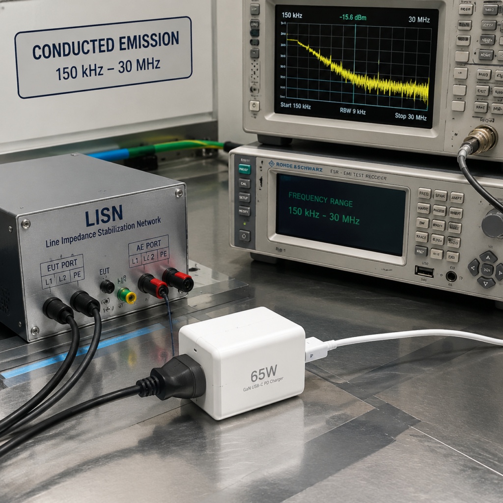
The conducted emission test measures interference propagating along wires, that is, the product transmits interference to the power grid through the power cord, affecting other devices on the same power grid.
- Reference standards: Test method refers to CISPR 16-2-1, product standards such as EU EN 55032, the conducted part of US FCC Part 15;
- Applicable ports: AC power input port (that is, the interface plugged into the wall);
- Typical parameters: The test frequency band is generally 150kHz~30MHz. During the test, a special isolation device (professionally called Line Impedance Stabilization Network, LISN for short) is used to block the interference inherent in the power grid, ensuring that only the interference emitted by the tested product is measured;
- Test method: Plug the tested product into the special isolation socket of the LISN, and detect the intensity of the interference signal in the power cord;
- Exceptions: Products without AC input are usually not tested according to AC power port items, but whether conducted disturbance testing is required for DC, vehicle-mounted or other external ports shall be determined according to applicable product standards and target market regulations. Vehicle chargers may also be subject to automotive environment standards or whole vehicle and component standards;
- Common causes of failure: The specifications of filter components of the switching power supply (such as X capacitor, Y capacitor, common mode inductor) are insufficient, or the layout of the PCB input loop is unreasonable.
Radiated Emission Test
The radiated emission test measures interference propagating through air, that is, whether the unintentional electromagnetic waves radiated by the product into the air will interfere with surrounding devices such as WiFi, Bluetooth headphones, and radios.
- Reference standards: Test method refers to CISPR 16-2-3, product standards such as EN 55032, the radiated part of FCC Part 15;
- Applicable objects: Charging products with digital circuits and high-speed data ports, such as PD fast chargers and USB-C cables with high-speed data;
- Typical parameters: The commonly used test distance is 3 meters or 10 meters. Different distances have different limits, and results cannot be directly compared across distances—for example, the limit measured at 3 meters will be higher than that at 10 meters, because the received signal is stronger when closer; the basic test frequency band generally starts from 30MHz;
- Test method: Place the product on a turntable in a shielded anechoic chamber, use an antenna to receive the electromagnetic waves radiated by the product. The turntable will rotate at different angles, and the antenna will also switch between horizontal and vertical polarization directions to scan the interference intensity of the entire frequency band;
- Exceptions: Pure passive cables or specific non-digital accessories may not be applicable to complete radiated emission testing, but this must be confirmed according to specific product standards, device definitions and target market regulations, and exemption cannot be judged solely by power;
- Common causes of failure: Poor termination of the shielding layer of the data cable, poor grounding of the charger shell, and too long high-speed signal loop.
Harmonic Current Test
The harmonic current test measures the product’s interference with the power grid waveform, that is, whether the product’s input current will deform the standard sine wave of the power grid and affect the normal operation of other devices on the same power grid.
- Reference standards: IEC 61000-3-2, EU EN 61000-3-2;
- Applicable ports: AC power input port;
- Typical parameters: Whether equipment with a rated input current of no more than 16A per phase is applicable to IEC/EN 61000-3-2 shall be judged according to the equipment category, connection method and standard exemption conditions, and 75W shall not be used as a general dividing line. The standard divides different limits and exemption conditions according to equipment categories;
- Test method: Let the product work under rated conditions, and detect the harmonic components of each order of the input current;
- Exceptions: Some low-power, specific categories of charging products may be exempted from this test according to standards;
- Common causes of failure: The input current waveform is not ideal, and the rectification, power factor correction (PFC) or control strategy design is insufficient.
Voltage Fluctuation and Flicker Test
The voltage fluctuation and flicker test measures whether the voltage change caused by product plugging/unplugging and power switching reaches the flicker evaluation limit specified by the standard. It is usually judged by indicators such as Pst and Plt, and is not equivalent to the fact that there must be visible light flicker in the actual test.
- Reference standards: IEC 61000-3-3, EU EN 61000-3-3;
- Applicable ports: AC power input port;
- Typical parameters: For equipment with a rated input current of no more than 16A per phase and connected to the public low-voltage power grid, whether this standard is applicable shall be judged according to the equipment category, connection method and standard exemption conditions. The limit is related to the voltage change rate and duration;
- Test method: Simulate the switching of different working states of the product, monitor the voltage change on the power grid side, and calculate the corresponding flicker evaluation indicators;
- Exceptions: Charging products with low power and minimal power change may be exempted according to standards;
- High-incidence scenarios: When the PD fast charging protocol switches power levels, or when multi-port loads are plugged and unplugged at the same time, voltage fluctuation exceeding the limit is most likely to occur.
EMS Electromagnetic Immunity Test Methods
EMS, or electromagnetic immunity, tests whether the product can withstand external electromagnetic interference. It is a required item for regulations such as EU CE-EMC. In the US market, it is mostly a voluntary requirement, but many large customers will specify it.
First, let’s talk about two core basic concepts:
- Test level: That is the intensity of interference applied to the product, such as the voltage of static electricity and the field strength of radiation. The higher the level, the stronger the interference;
- Performance criteria: There are three common levels A, B, and C in general standards, representing the state of the product after being interfered with:
- Level A: During and after the test, the product functions completely normally without any abnormality;
- Level B: Temporary functional abnormality occurs during the test, and it can recover by itself after the test without manual intervention;
- Level C: Functional abnormality occurs during the test, and it can only recover after manual restart or operation.
The specific qualification requirements shall be subject to applicable product standards, and not all products are required to reach Level A.
The following are common immunity test items for charging products:
Electrostatic Discharge (ESD) Test
The electrostatic discharge test simulates the electrostatic shock generated when the human body plugs and unplugs data cables or touches the product, for example, when you touch the charger after taking off a sweater in winter, will the static electricity zap damage the product.
- Reference standard: IEC 61000-4-2;
- Applicable positions: Exposed metal shells, USB/DC interfaces, buttons and other user-accessible positions;
- Typical parameters: Contact discharge 2kV~8kV, air discharge 2kV~15kV. The specific level is determined according to the product category and use environment;
- Test method: Use an electrostatic gun to perform contact discharge and air discharge on the test points respectively, and monitor the functional status of the product in real time at the same time;
- Exceptions: Products with fully insulated shells and no exposed conductive parts may simplify test points;
- Common failure phenomena: Charging interruption, fast charging disconnection, interface chip burnout, device restart.
Radiated Immunity Test
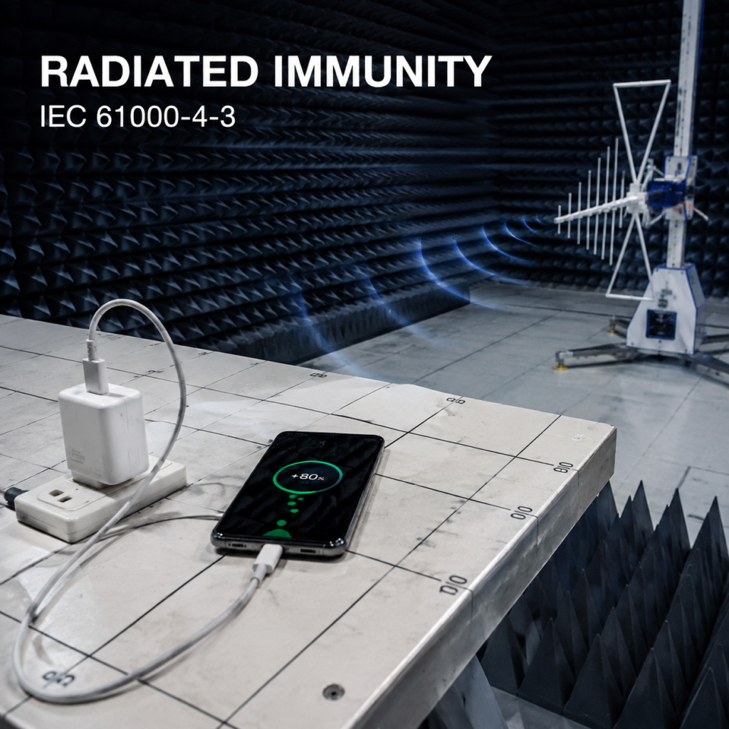
The radiated immunity test simulates the radio frequency electromagnetic field interference emitted by surrounding wireless devices such as mobile phones, walkie-talkies, and routers, for example, if you put a walkie-talkie next to the charger, will the charger stop charging.
- Reference standard: IEC 61000-4-3;
- Applicable objects: All charging products with electronic circuits and long cables;
- Typical parameters: Test frequency band 80MHz~6GHz, field strength 1V/m~10V/m. The specific level is determined according to the use environment, and the level of industrial environment is higher than that of household use;
- Test method: Use an antenna to emit interference waves of different frequencies to the product in a shielded anechoic chamber, and observe whether the product functions normally;
- Exceptions: Very simple passive accessories may be exempted, subject to specific standards;
- Common failure phenomena: Decreased charging power, data transmission packet loss, fast charging protocol disconnection, device disconnection.
Electrical Fast Transient/Burst (EFT) Test
The electrical fast transient/burst test simulates the dense small spike interference generated by the power grid when unplugging plugs, switch tripping, and relay pull-in, for example, when you unplug the plug of a hair dryer, will the charger on the same power strip be affected.
- Reference standard: IEC 61000-4-4;
- Applicable ports: AC power input port, some standards also require coverage of signal ports;
- Typical parameters: Test voltage 0.5kV~4kV, repetition frequency 5kHz/100kHz;
- Test method: Inject fast and repeated small pulses into the power cord through a coupling device, and monitor the functional status of the product in real time;
- Exceptions: Products with low-voltage DC power supply and no AC input usually do not need testing;
- Common failure phenomena: The charger restarts repeatedly, the charging power is unstable, and the fast charging protocol renegotiates.
Surge Test
The surge test simulates the high-energy large-voltage pulse that appears in the power grid during lightning induction and switching of large equipment, for example, when there is thunder in summer, a high-voltage pulse intrudes into the power grid, will it damage the charger.
- Reference standard: IEC 61000-4-5;
- Applicable ports: AC power input port (divided into line-line differential mode and line-ground common mode), some standards require coverage of DC output/signal ports. The differential mode here refers to the high-voltage pulse between the two power lines, and the common mode refers to the high-voltage pulse between the power line and the ground. The two have different simulation scenarios and different requirements;
- Typical parameters: AC port differential mode 0.5kV~2kV, source impedance 2Ω; AC port common mode 1kV~4kV, source impedance 12Ω; the specific level and terminal combination are determined according to the product category, whether there is a protective ground, and the use environment;
- Test method: Apply high-voltage pulses between the terminals of the corresponding ports, and observe the state of the product;
- Exceptions: Products with low-voltage DC power supply and no outdoor/power grid connection scenarios may have reduced levels or be exempted;
- Common failure phenomena: Fuse blown, power chip damaged, completely unable to work, insulation breakdown.
Conducted Radio Frequency Immunity Test
The conducted radio frequency immunity test simulates the scenario where interference is conducted into the product through cables such as power cords and data cables, for example, interference is transmitted from the USB cable to the charger, causing unstable charging.
- Reference standard: IEC 61000-4-6;
- Applicable ports: Applicable ports and cables shall be confirmed according to product standards. Usually, for power, signal or control cables with sufficient length that may conduct radio frequency interference, appropriate CDN, EM clamp or current clamp shall be selected. Short cables and specific USB ports may not be applicable, or require special configurations;
- Typical parameters: Test frequency band 150kHz~80MHz, test level 1V~10V, determined according to the use environment; coupling methods include CDN, EM clamp, current clamp, etc., which shall be selected according to the cable type, length and applicable standards;
- Test method: Inject radio frequency interference into cables that meet applicable conditions through a coupling device, and monitor the functional status of the product in real time;
- Exceptions: Products with very short cables and no exposed ports may simplify testing;
- Common failure phenomena: Data transmission packet loss, intermittent charging, frequent device disconnection.
Voltage Dips and Interruptions Test
The voltage dips and interruptions test simulates the scenario where the mains power drops for a short time, suddenly interrupts and then recovers, for example, when the home trips suddenly and then closes immediately, will the charger be damaged, and can fast charging recover automatically.
- Reference standard: IEC 61000-4-11;
- Applicable ports: AC power input port;
- Typical parameters: The test adopts the combination of residual voltage level and duration specified by the standard, for example, 0%, 40%, 70% or 80% residual voltage, and the duration is executed according to specified values such as half a cycle, one cycle, several cycles or hundreds of cycles; the specific shall be subject to applicable product standards;
- Test method: Simulate different degrees of voltage drop or power failure, and observe the output and recovery of the product;
- Exceptions: Products with low-voltage DC power supply and no AC input usually do not need testing;
- Key observation: Whether the fast charging protocol can reconnect normally, and whether the output will have overvoltage or overcurrent.
Differences in Test Focuses for Different Charging Products
Different types of charging products have different EMC test focuses. You don’t need to spend the same energy on all items, just focus on the key points.
Chargers/Power Adapters
Common evaluation items include conducted/radiated emission, ESD, EFT, surge and voltage dips/interruptions, but whether they are mandatory test items and the test level must be determined according to the target market regulations and applicable product standards.
Additional attention scenarios: Dynamic interference when multiple loads work at the same time, special noise under light load/no load, fluctuation when fast charging protocol switches.
Special requirements: Whether equipment with a rated input current of no more than 16A per phase is applicable to IEC/EN 61000-3-2 and 61000-3-3 shall be judged according to the equipment category, connection method and standard exemption conditions, and 75W shall not be used as a general dividing line. For harmonic exceeding the limit, the input current waveform, rectification/power factor correction and control strategy should be checked emphatically; voltage fluctuation and flicker shall be confirmed according to corresponding standards.
USB/USB-C Data Cables
- Passive charging cables (no chips): Tested along with the charger or terminal system, focusing on system-level radiated emission and ESD performance;
- For cables with signal conversion, retiming or active conditioning functions, independent evaluation or system-level verification shall be determined according to specific regulations and product standards; having a chip does not automatically mean that complete EMC testing must be completed as an independent active product;
- The 10Gbps transmission rate itself cannot be used as a basis for judging active cables, because 10Gbps USB-C cables may also be passive cables.
Additional attention scenarios: High-speed data transmission mode, performance of cables of different lengths, shielding layer termination quality (only for high-speed cables with shielding).
Notes: Passive low-speed charging cables do not need to apply the shielding requirements of high-speed data cables. Blindly adding shielding will only increase costs.
Multi-Port High-Power Fast Chargers
Core focus: Voltage fluctuation and flicker, multi-load dynamic interference, voltage dip recovery capability.
Additional attention scenarios: Noise changes when switching between different fast charging protocol levels and multi-port power distribution—for example, when three ports are charging at the same time, the power is dynamically distributed among the three ports, and the interference at this time may be greater than when a single port is fully loaded.
Charging Products with Data Transmission
Core focus: Radiated emission and conducted immunity in high-speed data mode.
Additional attention scenarios: Superimposed interference when data transmission and charging work at the same time—for example, when transmitting 10Gbps data while fast charging, the interference at this time is often more serious than when working alone.
Real Test Scenario Cases (Beginner Practical Reference)
After talking about so many test items, it may still be a bit abstract. Let’s use two common charging product test cases to help you understand how actual testing is done.
65W USB-C PD Multi-Port Charger Test Case
- Test configuration: Original AC power cord, 2 original USB-C charging cables, 2 electronic loads (simulating the loads of mobile phones and laptops respectively);
- Covered working modes: No load, single port 65W full load, dual ports full load at the same time, PD power level switching, load plugging and unplugging;
- Key test items: Conducted emission, radiated emission, surge, EFT, voltage dip, harmonic current;
- Typical most unfavorable scenario: When dual ports are fully loaded + PD level switching, the margin of conducted emission is the smallest, that is, it is most likely to exceed the limit—because the dynamic change of the power supply is the largest at this time, and the interference is the strongest.
USB-C Cable with 10Gbps Data Transmission Test Case
The 10Gbps transmission rate here itself does not mean that the cable is an active cable. If the cable has signal conversion, retiming or active conditioning functions, independent evaluation or system-level verification shall be determined according to specific regulations and product standards.
- Test configuration: Matching original charger, laptop, high-speed data tester, cables of two lengths: 1 meter and 2 meters;
- Covered working modes: Pure charging, pure data transmission, charging + data at the same time, cable straight/bent state;
- Key test items: Radiated emission, conducted immunity, ESD;
- Typical most unfavorable scenario: When charging + 10Gbps data are transmitted at the same time and the cable is in a bent state, the margin of radiated emission is the smallest—because bending may affect the continuity of the shielding layer, and the interference of charging and data transmission is superimposed together, making it easier to exceed the limit.
Advanced: Understanding EMC Test Reports and Result Validity
When you get an EMC test report, don’t be scared by the dense charts. Grasp the three core steps, and you can quickly judge whether the report is useful and whether the product is qualified.
3 Core Steps to Quickly Understand Test Reports
- Step 1: Check the applicable standards and test levels. First confirm whether the standard used in the report is the mandatory standard required by the target market, and whether the test level meets the requirements. For example, if you want to enter the EU, but the report uses the US FCC standard, then this report is useless to you.
- Step 2: Check the product configuration covered by the test. Confirm whether the sample in the report is consistent with your mass-produced product, and whether it covers common working modes, original accessories, typical load combinations, and port configurations—for example, the report tests single-port full load, but your product is mainly used with multiple ports at the same time, then the reference value of the result is limited.
- Step 3: Check the final judgment conclusion. For emission tests, look at “qualified/unqualified + margin”. The higher the margin, the better; for immunity tests, look at “test level + performance criterion result”. The higher the level and the better the criterion, the stronger the anti-interference ability of the product.
Qualification Judgment Logic for Two Types of Tests
Let’s emphasize the judgment logic of the two types of tests again to avoid misreading:
- EMI emission type: If the interference value is lower than the limit line, it is qualified. The higher the margin, the stronger the ability to resist part fluctuations during mass production;
- EMS immunity type: First look at the test level (that is, the interference intensity), then look at the performance criterion result—even if it is the same Level B criterion, Level B for 8kV static electricity definitely has stronger immunity than Level B for 4kV static electricity.
For charging products, the core items of concern are: conducted emission limit, radiated emission limit, ESD immunity level and criterion, surge immunity level and criterion. These are the places where problems are most likely to occur.
Common Causes of Invalid/Inaccurate Test Results
Not all EMC test reports are valid. In the following situations, the results may be inaccurate:
- Sample status problems: Using engineering samples, non-original accessories, or not produced according to mass production processes, the test results cannot represent the level of mass-produced products;
- Test configuration problems: Not covering the most unfavorable working modes, cable length/layout not meeting standard requirements, not using the coupling method specified by the standard, the results have no reference value;
- Test environment problems: The anechoic chamber/shielded room is not calibrated regularly, and external environmental interference is not completely shielded. The measured interference may include external ones, which is inaccurate;
- Operation process problems: Test equipment is not calibrated, testers do not operate according to standard steps, and the function monitoring method does not meet the requirements. For example, only checking whether there is output, not monitoring whether the fast charging protocol is disconnected, will lead to missed judgments.
Common Misconception Avoidance and Quick Troubleshooting for Unqualified Results
If the test is unqualified, don’t panic. We have sorted out the troubleshooting directions for the 6 most common unqualified phenomena of charging products to help you quickly locate the problem.
| Test Unqualified Phenomenon | Priority Inspection Direction | Verification Method | Attention Boundary |
|---|---|---|---|
| Conducted emission exceeding the limit | Specifications of input filter components (X/Y capacitors, common mode inductors), PCB layout of power input loop, switching frequency selection | Re-select components under the premise of meeting safety, rated voltage, capacitance, leakage current, temperature rise, impedance and reliability requirements, adjust the input loop wiring, and confirm through design verification and retesting | If the exceeding frequency point is in the radiated frequency band, it is necessary to simultaneously check the radiation coupling problem, not just focus on input filtering |
| Radiated emission exceeding the limit | Shielding layer and termination quality of high-speed data cables, interface grounding condition, shielding continuity of charger shell, high-speed signal loop length | Evaluate cables, grounding and structural design under the premise of meeting interface, electrical safety, signal integrity and reliability requirements, and retest after optimization | If passive low-speed charging cables exceed the limit, priority should be given to checking the interference at the charger end, not the cable itself |
| ESD test failure (restart/disconnection/damage) | Specifications of interface ESD protection devices (TVS tubes), shell grounding design, discharge path of interface metal parts, immunity of protocol chips | Add or adjust TVS tubes, optimize the grounding path, and confirm the capacitance, working voltage and safety parameters of the protection devices before retesting | Air discharge failure may be related to shell gaps and insulation thickness, not just circuit problems |
| Surge test failure (damage/no output) | Specification selection of varistors, fuses, gas discharge tubes, surge discharge path, PCB insulation distance | Re-select components under the premise of meeting safety, rated voltage, protection level, energy capability, failure mode, fuse coordination and primary-secondary insulation requirements, and confirm through design verification and retesting | For Class II chargers without protective ground, common mode surge should focus on primary-secondary insulation design |
| Fast charging/data protocol disconnection during immunity test | Immunity design of protocol chips, power output filtering, cable shielding effect, interface signal integrity | When adding output filtering or replacing shielded cables, it is necessary to simultaneously check rated parameters, leakage current, temperature rise, impedance, signal integrity and reliability, and then retest after completion of verification | It is necessary to first distinguish whether the disconnection is caused by emission interference or insufficient immunity, and the rectification directions of the two are different |
| No recovery after voltage dip | Undervoltage protection design of power control chip, output capacitor capacity, protocol restart logic | When adjusting the output capacitor or undervoltage protection threshold, it is necessary to simultaneously confirm surge current, temperature rise, safety and reliability requirements, and then retest after verification | If the applicable standard allows Level B criterion (self-recovery), there is no need to rectify to Level A, to avoid over-design |
Basic Methods to Reduce Test Failure Rate
If you want to spend less wrong money and improve the first-pass rate, you can start from these basic aspects:
- Before sending for testing, assemble the original accessories into a complete use system. Do not test with scattered parts, otherwise the results will be inaccurate;
- Clarify the standard requirements of the target market in advance, do not blindly send for testing irrelevant items, wasting time and money;
- For core components, prioritize supplier products with EMC design references. For example, if the power chip manufacturer has a reference design, EMC is easier to pass;
- Before formal testing, you can do a simple pre-check, such as using a near-field probe to scan for obvious interference sources, and modify them in advance, so as to avoid retesting due to unqualified formal testing;
- Reserve 1~2 rounds of rectification and retesting time. Do not send for testing just before the project deadline, to avoid delaying the progress due to one failure.
Learning Summary
After reading this article, you should be able to independently complete these basic judgments:
- Can distinguish the two core categories of EMC—EMI electromagnetic interference emission and EMS electromagnetic immunity, and know the respective test purposes of the two;
- Can initially judge whether separate testing is required and what the core test items are according to different product types such as chargers, USB-C cables, and multi-port fast chargers;
- Can initially select corresponding EMC regulations, standards and conformity paths according to target overseas markets such as the EU and the US;
- Can understand the qualification conclusion, margin, test level and performance criterion of basic EMC test reports;
- Can avoid 6 common cognitive misconceptions in EMC testing of charging products;
- Can make preliminary cause location and rectification direction judgments for 6 types of common EMC unqualified phenomena;
- Can independently plan the basic preparation work before sending charging products for testing, effectively reducing the test failure rate.
EMC testing seems complicated, but in fact, the core is around the two basic points of “not interfering with others, not being interfered with by others”. For charging products, as long as you grasp the core test items and make preparations in advance, you can avoid many pitfalls.