
Overseas sellers or R&D teams working on charging products have most likely run into pitfalls with EMC certification: after sending samples to a third-party lab, the results show excessive radiated emissions, so you have to go back to modify the board, replace cables, and resubmit for testing. This not only increases costs but may also delay time to market. In fact, before the formal compliance assessment, you can conduct a round of EMC pre-regulatory testing — equivalent to a practice exam before certification — to identify some obvious EMC risks in advance at a relatively low cost. This guide explains the entire EMC pre-testing process for charging products from beginner to advanced levels, so even if you have never been exposed to EMC before, you can understand how to get started.
Core Beginner Understanding: What Exactly is Pre-Testing?
First, let’s clarify the most basic concept: EMC is the abbreviation for Electromagnetic Compatibility. Simply put, electronic equipment must “neither interfere with others nor be interfered with by others” — the former is called EMI (Electromagnetic Interference), which refers to whether the electromagnetic noise emitted by the device interferes with surrounding equipment; the latter is called EMS (Electromagnetic Susceptibility), which refers to whether the device can operate normally without damage when subjected to external electromagnetic interference.
EMC pre-regulatory testing, also called pre-conformance testing or pre-compliance testing, is essentially an internal practice exam before the formal compliance assessment: using relatively simple equipment and sites to assess the product’s EMC performance in advance, identify obvious problems and rectify them first, so you don’t have to wait until formal testing to encounter pitfalls.
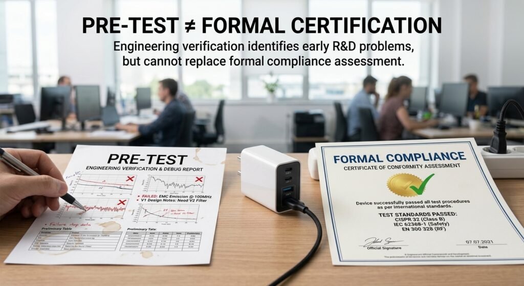
Many people confuse pre-testing with formal compliance assessment, but in fact the core differences between the two are significant. We have organized them into a table for easy comparison:
| Comparison Dimension | EMC Pre-Regulatory Testing | Formal EMC Compliance Assessment or Authorized Testing |
|---|---|---|
| Core Purpose | Internal assessment and early rectification | Supports completion of formal conformity assessment, declaration of conformity, or FCC equipment authorization under applicable regulations |
| Test Environment | Simple site / ordinary room | Test site or laboratory configured in accordance with applicable standards |
| Legal Effect | Usually cannot replace the formal conformity assessment or FCC equipment authorization required by regulations, but can be used as auxiliary evidence for engineering verification and technical documentation | Complete the corresponding conformity assessment or equipment authorization in accordance with the regulations of the target market and equipment category |
| Cost | Usually lower than full formal testing, but there is no uniform ratio for fees; quotations should be based on projects, equipment, sites, and rectification rounds | Charged based on test items, laboratory, market, and rectification retesting situations |
Why Charging Products Must Undergo Pre-Testing
For charging products such as chargers, USB-C cables, and power adapters, EMC pre-testing is usually necessary — because these products are inherently high-risk categories for EMC. There are two core reasons: first, the switching power supply in the charger is a high-frequency noise source, especially the currently popular gallium nitride (GaN) chargers, which have higher operating frequencies and are more likely to generate strong interference; second, USB/USB-C cables themselves may form long coupling paths or radiation structures, which can easily radiate internal interference or conduct external interference in.
In actual scenarios, EMC problems can range from minor issues such as static noise in nearby headphones or speakers, intermittent charging, and failed data transmission, to severe issues such as interface chips being damaged by static electricity, or even safety hazards. The biggest benefit of conducting pre-testing in advance is reducing the cost of certification rework, and it can also help shorten the product’s time to market.
Four Common Cognitive Misconceptions for Beginners
People who are new to pre-testing often have several typical misunderstandings, which are clarified here once and for all:
- “Pre-testing is random and completely useless”: If the method, sample status, and test configuration are reasonable, even engineering pre-scanning can help identify some obvious interference problems, and is especially suitable for early investigation of items such as radiated and conducted emissions. However, it cannot replace formal testing conducted in accordance with standards.
- “Passing pre-testing means 100% passing formal certification”: There are gaps between pre-testing environments and equipment accuracy and those of formal laboratories; the results can only be used as engineering reference and cannot guarantee that the formal assessment will definitely pass.
- “Only high-power charging products need it”: Even a 20W low-power charger may have excessive radiated or conducted emissions if the switching frequency design is unreasonable or if it is paired with a high-speed data cable; there is no absolute relationship with power level.
- “A product that charges normally equals EMC compliance”: Many EMC problems are hidden: for example, interference with surrounding equipment, which you may not notice in daily use; another example is electrostatic damage, which only triggers in dry environments, but is a mandatory requirement in certification. You cannot replace testing with daily usage experience.
Test Boundary Definition: What to Test, What Standard to Follow, What to Test First
Now that you understand the basic concepts of pre-testing, the next step is to clearly define the test boundaries — what category your product belongs to, which market’s standards to test against, and what to test first and what to test later. Otherwise, it is easy to waste time on useless tests or miss required tests.
Scope of Products Under Test (Charging Product Specific)
For charging products, the objects of pre-testing are mainly divided into three categories, which should also be adjusted according to functional differences:
- Power supply category: Includes chargers, power adapters, car chargers, and power banks. These products usually require focus on the EMC performance of the switching power supply, input ports, and output ports;
- Cable category: Includes separately sold or bundled USB/USB-C charging cables and data cables. Whether a cable requires independent EMC testing depends on the regulations of the target market, product standards, whether the cable contains active electronic components, and its typical usage configuration;
- System combination: The actual usage combination of charger + cable + terminal (such as a mobile phone or laptop). In many cases, individual products have no issues, but interference occurs when used together. If conditions permit, it is best to evaluate representative combinations of actual usage.
For cables, you cannot simply assume that “if sold separately, they must be tested separately; if sold as a bundle, they can definitely be tested with the whole device”. If the cable contains active electronic components, or its EMC performance obviously depends on the host, charger, and terminal, the cable itself and its representative combinations should be evaluated in accordance with the requirements of the target market.
In addition, functional differences of products should also be considered: products that only supply power, those that supply power plus data transmission, and those with PD fast charging or a display all have different test items and severity levels. For cables with high-speed data transmission, it is usually necessary to focus on radiated emissions and combination configurations under high-speed operating conditions.
Standard Framework Corresponding to Target Markets
Many people confuse regulations and standards. Let’s clarify first: Regulations are mandatory legal requirements, such as the EU EMC Directive and the US FCC Part 15; while standards are the technical basis for testing and judgment. Different products, markets, and equipment categories may be subject to different regulations and standards, and the two cannot be confused.
Specifically for mainstream markets:
- EU market: First, it is necessary to determine whether the product falls within the scope of the EMC Directive, and then select the corresponding harmonized standard according to the product category. The applicable standards for chargers, power adapters, terminal equipment, and cables may be different, and EN 55032 cannot be uniformly applied to all. CE is also not a single standard or a unified “official certification project”; manufacturers usually need to complete conformity assessment, technical documentation, and EU Declaration of Conformity under applicable regulations.
- US FCC: FCC Part 15 mainly specifies radio frequency emission limits and equipment authorization requirements. Unintentional radiating devices are usually tested in accordance with applicable FCC clauses and methods such as ANSI C63.4; FCC testing cannot be equated with a complete EMC emission and immunity assessment. Depending on the equipment category, different equipment authorization methods such as Supplier’s Declaration of Conformity or Certification may be involved.
- Other markets such as the UK, Canada, and Australia: May adopt international standards, national regulations, or corresponding national transposed standards; specific requirements should be confirmed according to product category and target market.
Emission test methods in some markets may be similar, but regulatory scope, equipment classification, limits, test distance, detectors, port requirements, immunity requirements, and authorization methods may still differ. Therefore, you cannot use a fixed 3 dB difference to generalize across markets, nor can you directly infer compliance in other markets from the test results of one market. You must verify the regulations, product classification, limits, and authorization requirements of each target market one by one.
How to Prioritize Testing
Many people want to test all items at the beginning, but in fact, you can test according to risk priority first, which saves time and focuses on key points:
- Sorted by risk: EMI emissions > electrostatic discharge immunity > other EMS immunity items — in formal assessments, emission problems are usually more common, and electrostatic discharge is also an item that requires key attention for charging products;
- Selected by product: For power supply products such as chargers and power adapters, conducted emissions are tested first; for high-speed data cables such as USB 3.0/4.0, radiated emissions are tested first;
- Selected by power supply conditions and standards: Whether AC input products need to test harmonics and voltage fluctuations should be judged according to the applicable conditions of IEC 61000-3-2 and IEC 61000-3-3, combined with input current, equipment category, and power supply conditions. Immunity items such as surge and EFT should be determined according to applicable product standards, ports, and installation environment, and cannot be divided solely by 65W or 100W.
Four Principles for Test Scope Judgment (Intermediate Level)
If you already have a certain foundation and want to define the test scope more accurately, you can remember four principles:
- Determine the test object according to the regulations of the target market, product standards, whether the cable contains active electronic components, and its typical usage configuration; if necessary, evaluate the combination of the cable with a representative host or charger;
- Products with data transmission should cover the highest rate transmission state, and cannot only test the charging mode — radiated interference during high-speed transmission may be more obvious;
- For multi-port fast charging products, representative extreme modes such as single-port full power and multi-port total power should be tested — different output combinations may change the operating status of the switching power supply and protocol chip;
- It is best to organize a “product-market-test item” comparison table by yourself, listing the test items for each model corresponding to each market, to avoid missing tests.
Core Pre-Test Items and High-Risk Points for Charging Products
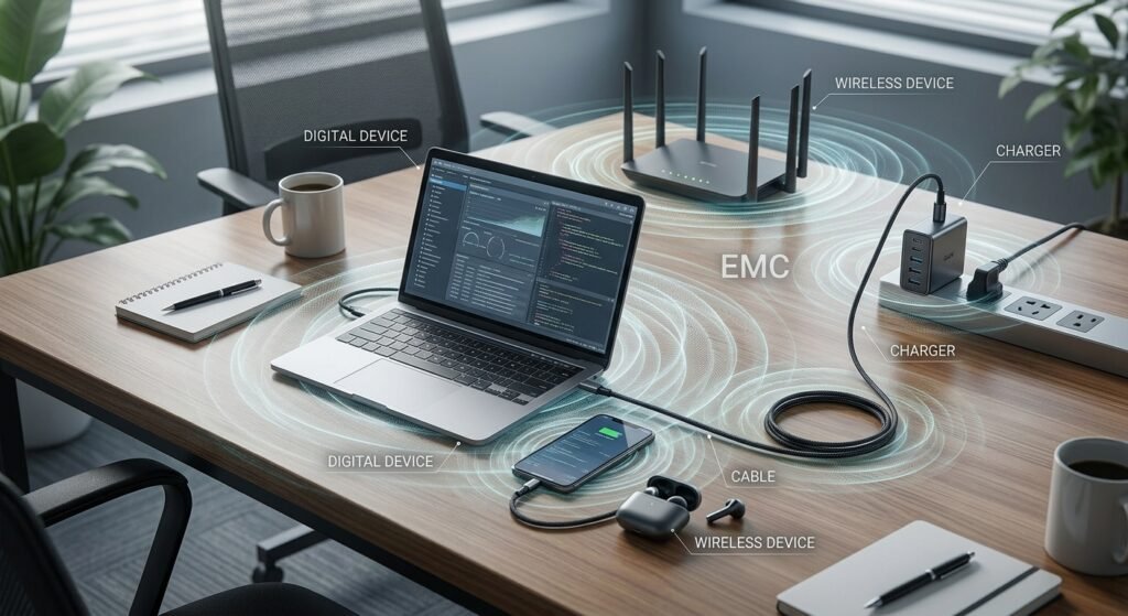
After clearly defining the boundaries, let’s look at the core items of pre-testing and where the high-risk points for charging products are.
Core EMI (Electromagnetic Interference) Items (Must-Do for Beginners)
EMI is a part that requires key attention in formal assessments. At the beginner stage, focus on three test items:
- Conducted emission test: Checks whether the interference transmitted by the product through power cords and data cables will pollute the power grid or affect other devices on the same power strip or same interface. 150kHz-30MHz is a common frequency band in some AC port conducted emission tests, but the specific range and port requirements should be confirmed according to applicable standards. High-risk points for charging products are the AC input end, multi-port fast charging, and high-frequency switching power supplies.
- Radiated emission test: Checks whether the electromagnetic interference emitted by the product through the air will affect surrounding electronic equipment — for example, static noise in a nearby radio while charging may indicate the presence of radiated interference, but you cannot judge whether it exceeds the limit based on this alone. 30MHz to 1GHz is a common frequency band in some radiated emission tests, but the full frequency range should be determined according to applicable standards, maximum operating frequency, digital interfaces, and wireless functions. High-risk points include high-speed data cables, interfaces, switching power supplies, and high-frequency clock circuits.
- Harmonic current and voltage fluctuation (optional): Checks the impact of AC-powered products on the public low-voltage power grid. Whether AC input products need to be tested should be judged based on the IEC/EN standard version adopted by the target market, input current, equipment category, and power supply conditions, and 65W cannot be used as a general threshold.
Core EMS (Electromagnetic Susceptibility) Items
EMS tests the product’s ability to withstand external interference. At the beginner stage, you can first focus on electrostatic discharge immunity, and other items are selected according to applicable standards and product use:
- Electrostatic discharge immunity (ESD, must-do for beginners): Simulates static electricity generated when the human body touches or approaches the product, to see if it will cause charging interruption, restart, or even damage. Testing usually includes contact discharge and air discharge: contact discharge is applied to conductive surfaces accessible to users, and air discharge is applied to insulating surfaces accessible to users. It may also include indirect discharge to positions such as horizontal coupling plates and vertical coupling plates. The specific level, number of times, position, and operating status should be determined in accordance with IEC 61000-4-2 and applicable product standards. Do not treat inaccessible internal pins of USB-C as a universally required test point.
- Advanced optional immunity items: Electrical Fast Transient (EFT, simulates fast pulses generated by power switching or plugging/unplugging), surge immunity (simulates high-energy surges from lightning induction or large power grid fluctuations), radio frequency immunity (simulates interference from wireless signals such as mobile phones and base stations to the product). These items should be determined according to applicable product standards, ports, and usage environment, and cannot be determined solely by product power.
Must-Do Pre-Test Item List for Beginner Charging Products
For the vast majority of charging products, you can first do 3 core tests at the beginner stage: conducted emissions, radiated emissions, and electrostatic discharge immunity. Whether AC input products need additional testing for harmonics and voltage fluctuations should be judged based on IEC 61000-3-2, IEC 61000-3-3, and the product standards adopted by the target market, combined with input current, equipment category, and power supply conditions.
Whether to add immunity items such as surge and EFT should be determined according to applicable product standards, AC ports, usage environment, and target market requirements, rather than judged solely by 100W. For high-speed data cables such as USB 3.0/4.0, additional attention should be paid to radiated emissions and representative combination configurations under the highest rate operating state.
Pre-Test Preparation: Environment, Samples, Equipment, and Checklist
Before officially starting the test, you must first prepare the environment, samples, and equipment. Otherwise, the test results are likely to be inaccurate, and you will be working in vain.
Entry-Level Pre-Test Environment Requirements
For entry-level pre-testing, you don’t need to build a dedicated shielded anechoic chamber at the beginning. Find a room with less interference, which can be used for engineering pre-scanning and problem location, but it must be clear that it cannot be directly equated with a standard test site:
- Site: Stay away from mobile phones, base stations, and high-power equipment. Try not to place extra electronic equipment in the room, and there should be no large areas of metal on the ground or around. Ordinary rooms may still have systematic errors caused by reflection, background noise, and site factors;
- Power supply: Use a stable power supply suitable for testing, and record the input conditions to avoid clutter in the power grid affecting the results;
- Basic configuration: There must be an insulated tabletop, and an adjustable electronic load (used to simulate the full-power charging state of the product, which is more stable than connecting a real mobile phone);
- Background noise requirements: It should be confirmed that the background noise is sufficiently lower than the signal under test, and the measurement system, site, and uncertainty should be recorded. Background noise 6dB below the target limit is not a universally applicable compliance or credibility criterion; test results in ordinary rooms are mainly used for trend location, and you cannot judge credibility or compliance based solely on this rule.
Charging Product Test Sample Preparation Requirements
The preparation of test samples is also particular, otherwise the test results will have no reference value:
- Sample status: Use samples with normal functions that are close to the mass production version, paired with original or standard charging cables — if you use engineering prototypes or randomly find a cable for testing, the results may be very different from the mass production version;
- Operating mode: Confirm the most severe operating state of the product in advance, such as full power output, highest rate transmission, and simultaneous multi-port output. Adjust to these representative states during testing, otherwise problems may not be detected;
- Sample quantity: 1-2 units can be used for early engineering investigation, but cannot represent all mass production differences. Do not only pick the best-made “golden samples”; representative samples should be selected in combination with batches and configurations;
- Precautions: If it is an engineering prototype, be sure to clearly mark the software and hardware versions. If there is a major revision later, testing must be repeated, and previous results cannot be used.
Selection Logic for Common Pre-Test Equipment
Pre-test equipment should be selected according to purpose; the equipment required for locating interference sources is different from that for estimating limits:
- Interference source location equipment: Near-field probes and spectrum analyzers are suitable for observing frequency changes, comparing different design schemes, and locating interference sources near switching tubes, transformers, and interfaces;
- Limit estimation equipment: If you need to estimate results close to formal testing, you should use a system with appropriate calibration, antenna factor, LISN/AMN, and measurement software or receiver, and confirm that the measurement distance, frequency range, and detector meet the target standard;
- Electrostatic test equipment: ESD pre-testing should use equipment that meets the requirements of IEC 61000-4-2 and is calibrated. Ordinary electrostatic guns may not be able to guarantee the specified discharge waveform, level, and repeatability;
- Immunity equipment: Surge, EFT, and radio frequency immunity equipment are expensive and have high operational requirements. At the beginner stage, you can prioritize outsourcing to laboratories with corresponding equipment and experience.
The purchasing principle is very simple: if you are just looking for interference sources, near-field probes and spectrum analyzers can be used as engineering tools; if you need to compare against limits, you cannot just look at the relative readings on the instrument screen, but must use a calibrated and fully configured measurement system.
Five Must-Do Checks Before Pre-Testing
Before officially starting the test, be sure to do a check first to avoid wasted testing:
- Whether the sample function and load are normal, and whether it has been adjusted to the target operating mode;
- Whether interference sources in the environment (mobile phones, routers, air conditioners, etc.) have been turned off;
- Whether the test equipment has undergone basic calibration;
- Whether the cable placement is consistent with actual use, naturally straightened, and not coiled;
- Whether the terminal equipment (mobile phone/computer) used for testing has a fixed model and fixed status.
Entry-Level Pre-Test Operation Steps (Charging Product Specific)
After the preparation work is done, we can start the entry-level engineering pre-scanning. The following is the basic idea for charging products. When it comes to formal limit judgment, ESD, EFT, and surge, it should be completed by personnel or laboratories with corresponding equipment, calibration conditions, and safety measures.
Radiated Emission Pre-Test Operation
Step 1: Place the sample in the center of the insulated tabletop, connect the electronic load, and adjust to the full power output state; if it is a product with data transmission, also adjust to the highest rate transmission state. The USB-C cable should be naturally straightened, not stuck to the metal tabletop, and consistent with the target usage configuration.
Step 2: If using a near-field probe, it should be used to scan the sample surface, cables, and near interfaces to locate the main interference sources. The reading of a near-field probe 30cm from the sample cannot be directly compared with formal radiated emission limits, nor can it be directly converted with formal 3m or 10m field strength measurements.
Step 3: If quantitative site pre-scanning is to be performed, the measurement distance, antenna, antenna factor, frequency range, antenna height, and direction changes should be set according to the target standard, and corresponding calibration data should be used. Peak scanning can be used to quickly find candidate frequency points, but cannot be directly used as a conclusion of “exceeding the limit”; ultimately, it must be rechecked using the specified detector in accordance with applicable standards.
Step 4: Record the candidate frequency points, interference intensity, measurement configuration, and corresponding product operating mode for subsequent rectification.
Special attention should be paid to charging products: do not only test the full power state; the three states of no-load, full load, and protocol switching must all be covered — in many cases, the interference during protocol switching (such as PD fast charging negotiation) is even greater than at full power. If you have no professional equipment at all, you can also use an ordinary FM radio close to the sample to listen for obvious static noise, as a non-quantitative fault clue. However, radios cannot locate frequencies, measure field strength, or judge compliance with any regulatory limits, and cannot be used to determine whether radiated emissions are qualified.
Conducted Emission Pre-Test Operation
Step 1: Conducted emissions at the AC input end should usually use a Line Impedance Stabilization Network/Artificial Mains Network (LISN/AMN) that meets applicable standards and a specified measurement receiver, then connected to a power supply suitable for testing. LISN/AMN is not only used for connection measurement, but also provides specified impedance, isolates external power supply interference, and serves as a measurement port. For other ports, the specified coupling network should be selected according to corresponding standards, and the results of ordinary conducted coupling devices cannot be directly compared with limits.
Step 2: Adjust the sample to the full power output state. If it is a multi-port fast charger, also test representative modes such as single-port full power and multi-port total power separately.
Step 3: For AC ports, peak pre-scanning can be performed first according to the applicable frequency band of the target standard, and after finding candidate frequency points, recheck with the specified detector. 150kHz-30MHz is a common frequency band in some AC port conducted emission tests, but the specific range shall be subject to the target standard.
Step 4: Record the interference value, corresponding frequency point, as well as the input voltage, load conditions, LISN/AMN configuration, and cable layout at that time.
Note for charging products: Conducted emissions need to test the three states of no-load, half-load, and full-load at the same time. It is not only full-load that may exceed the limit; some products have even greater interference at half-load.
Electrostatic Discharge Pre-Test Operation
Step 1: Place the sample on an insulating support suitable for testing, and maintain the normal charging or data transmission operating state.
Step 2: According to IEC 61000-4-2 and applicable product standards, determine the test positions accessible to users, discharge level, number of times, and operating state. Apply contact discharge to conductive surfaces accessible to users, and air discharge to insulating surfaces accessible to users; indirect discharge such as horizontal coupling plates and vertical coupling plates should also be considered as required.
Step 3: Do not treat inaccessible internal pins of USB-C as a universally required test point. Direct discharge to internal pins of connectors or other inaccessible parts may not conform to the test objects specified in the standard, and may also damage samples and equipment. Positions such as connector shells, exposed metal parts, shell gaps, and buttons that are accessible to users should be evaluated according to product structure and standard requirements.
Step 4: Observe whether the sample has abnormalities, such as charging interruption, restart, data disconnection, permanent damage, etc., and record them. The results are best divided into three categories: those that can recover automatically, those that require manual restart, and those that are permanently damaged. The severity is different, and the rectification priority is also different.
Pre-Test Result Interpretation and Validity Judgment (Intermediate Level)
After testing, how to interpret the results? Are the results accurate? Can they pass the formal compliance assessment? This section helps you judge the reference value of the results and the engineering risks.
Basic Result Reading Method
The core logic is: Do not use unvalidated fixed “relaxation values” to replace formal limits. There may be differences in measurement distance, antenna, site, cable layout, instrument calibration, and measurement uncertainty between pre-conformance testing and formal testing.
- Determination of engineering margin: Internal engineering margins should be set based on the measured correlation between the pre-conformance system and the formal test system, calibration data, and measurement uncertainty. There is no fixed 6-10dB or 3-6dB relaxation rule applicable to all open environments, shielded boxes, or professional sites;
- Preliminary judgment: If in a system highly correlated with the formal method, the test result is below the formal limit with a verified engineering margin, the risk is usually low; if it is close to or exceeds the limit, rectification should be arranged or sent to a professional laboratory for recheck;
- Measurement caliber: Peak scanning can be used to quickly find candidate frequency points; compliance judgment must be directly measured using the specified quasi-peak, average, or other detectors in accordance with applicable standards, and cannot rely on general conversion. A peak value higher than the limit does not necessarily mean that the quasi-peak or average value exceeds the limit, but it should be retested with the specified detector.
Engineering margins should usually be set below the formal limit, rather than regarding results higher than the formal limit as safe. Quantitative comparison is only suitable when the measurement chain, distance, unit, and calibration data all correspond to the target standard and correlation verification has been completed. Near-field readings in ordinary rooms usually cannot be directly compared with far-field limits in dBμV/m.
Common Error Sources for Charging Products
Many people get inaccurate test results mostly due to these types of errors:
- Environmental error: Unclosed electronic equipment around, metal reflections on walls and floors, and too high background noise will all affect the results;
- Equipment error: Uncalibrated test equipment, incorrect antenna position and angle, and inaccurate probe distance will all affect the values;
- Sample error: Not adjusted to the most severe operating mode, coiled cables or incorrect cable length, and samples being engineering prototypes rather than mass production versions will naturally lead to inaccurate results;
- Systematic error: Only testing a single charger or a single cable, not testing the combined state of charger + cable + terminal — in actual use, they are used together, and it is very likely that individual products have no issues, but interference occurs when combined.
How to Judge the Reference Value of Results
The reference value of pre-testing depends on the correlation between the test system and the formal method, calibration, site, measurement distance, cable layout, operating mode, and measurement uncertainty. It should not be expressed as a unified percentage such as “70%-80%”.
The closer the following conditions are, the more engineering reference value the results usually have:
- There are no obvious additional interference sources in the test environment, and the background noise is sufficiently lower than the signal under test;
- The sample status, wiring method, and operating mode are all consistent with the requirements of formal testing;
- The test equipment has undergone basic calibration, and the test distance, frequency band settings, antenna factor, and detector are all consistent with the target method;
- The test records are complete, and the same configuration can be repeated to compare the results before and after rectification.
If only no-load was tested, cables were placed randomly, there are a lot of metal and interference sources in the environment, or a near-field probe was used to directly compare with far-field limits, then the reference value of the results is very low. They can only be used to find approximate interference sources, and cannot be used to judge whether the formal compliance assessment can be passed.
Result Risk Classification Method
Engineering teams can formulate internal risk margins based on verified system correlation, measurement uncertainty, sample differences, and rectification goals. For example:
- High risk: Candidate frequency points are close to or exceed the formal limit in measurements consistent with the formal method, or the product has obvious functional abnormalities;
- Medium risk: Although the result is below the limit, there is no verified engineering margin, or there is large fluctuation between different operating modes, samples, and cable configurations;
- Low risk: Under representative worst-case configurations, the results are stably below the formal limit, and the test system has sufficient correlation with the formal method.
These margins are only used for engineering decision-making and cannot replace formal standard limits, specified detectors, and complete test methods.
Common Problem Troubleshooting and Pitfall Avoidance Guide (Intermediate Level)
If the test fails, how to troubleshoot the problem? What are the common pitfalls when doing pre-testing? This section helps you avoid detours.
Preliminary Troubleshooting Logic for Failures
For different test items, the troubleshooting ideas are different:
- Troubleshooting excessive radiated emissions: Under the premise of maintaining complete test configuration and records, comparative positioning can be performed by changing cable shielding, length, termination, and layout. Improvement after changing cables can only indicate that the cable configuration affects the results, and cannot alone prove that the problem must come from insufficient shielding or cable antenna effect. After that, a near-field probe can be used to scan switching tubes, transformers, and interface positions to locate specific interference sources; when confirming the rectification effect, the representative cables and configurations specified in the target standard should be restored.
- Troubleshooting excessive conducted emissions: The first step is to check whether the power input filter circuit (common mode inductor, Y capacitor) is complete and whether the parameters are correct. Many conducted problems are caused by poor filtering; the second step is to adjust the load size to confirm the operating state corresponding to the excess; the third step is to compare the shielding, length, and layout of the input cables while maintaining the specified test configuration. You cannot directly compare the results with the original test conclusion after randomly replacing cables.
- Troubleshooting electrostatic discharge failure: The first step is to check whether the USB interface has electrostatic protection devices (such as TVS tubes); the second step is to check the connection between metal parts and the chassis or ground according to the equipment’s grounding category, insulation system, and ESD return path. Not all metal parts must be connected to protective earth, especially Class II double-insulated equipment cannot be uniformly required to be connected to protective earth; the third step is to test different discharge positions to confirm the path of interference entry.
- Troubleshooting immunity test abnormalities: The core logic is to first find the interference entry point (power cord/data cable/interface), then check the sensitive circuit. Common situations for charging products are: charging interruption and restart are mostly related to interference with the power supply or protocol chip, and data disconnection is mostly related to interference with the interface and data channel, but the specific cause still needs to be confirmed in combination with waveforms, operating status, and circuit structure.
Five Common Pitfalls in Pre-Test Operations
When doing pre-testing, there are several very common pitfalls that many people have fallen into:
- Only testing no-load/half-load, not full power/highest rate: Some people even think that low-load interference is small and does not need to be tested. In fact, in many cases, interference during protocol switching and low-load states is even greater, and all representative extreme states must be covered;
- Cables are randomly coiled: Especially for USB-C cables, the radiation characteristics will change after being coiled, and the test results may have no reference value. They must be arranged according to the target usage configuration;
- Not recording the test environment and configuration: When the results exceed the limit, you don’t know if it’s a product problem, a change in the environment, or a different sample status, and you can’t review it at all;
- Changing multiple places in one rectification: Replacing inductors, adding shielding, and changing cables at the same time, in the end you don’t know which measure works, and it may also transfer interference from one frequency band to another, making it more and more chaotic. A more reliable approach is to change one main factor at a time, retest after the change, and continue after confirming it is effective;
- Only testing individual products, not combined states: In many cases, individual products have no issues, but interference occurs when combined, because cables and terminals may change common mode current and radiation paths, amplifying interference.
Common Limitations of Rectification Measures
Rectification is not just adding a filter or shielding. Many rectification measures have side effects, which should be considered in advance:
- Adding filter devices may increase voltage drop and heat generation, and also increase volume and cost;
- Adding a shielding layer may affect heat dissipation, increase assembly difficulty, and attention must also be paid to insulation distance, otherwise there will be safety hazards;
- Replacing with shielded cables may affect fast charging protocol negotiation, or reduce data transmission rate, and may also affect plugging and unplugging durability;
- Rectification in a single scenario may not cover all usage modes. For example, single-port output is fine, but interference occurs again when multiple ports are used together. After rectification, all states must be retested.
Decision Suggestions: Self-Testing vs. Professional Laboratory
Many people struggle: should I test by myself, or find a professional laboratory? Should I build my own laboratory, or outsource? Here are clear decision criteria for you.
Scenarios Suitable for Beginner Self-Testing
If you fall into these situations, you can do engineering pre-scanning and problem location by yourself under the premise of having appropriate equipment, calibration, and safety measures:
- The product is still in the early stage of R&D, and you need to quickly locate interference sources without too accurate results;
- The budget is limited, and you want to first eliminate obvious problems before sending for formal testing to reduce the risk of rework;
- You have many product models, and you want to do an initial screening first, select higher-risk models, and then focus on testing them;
- You want to quickly verify the effect after rectification, without sending to the laboratory every time, saving time and money.
Scenarios Requiring a Professional Laboratory
If it is these situations, it is recommended to directly find a professional laboratory for pre-testing or formal testing:
- The formal compliance assessment is about to be submitted soon, and results closer to standard methods are needed to judge the risk;
- The self-test results are near the limit, and you are not sure if you can pass. At this time, the results of a professional laboratory are more credible;
- The product contains high-speed digital interfaces, active electronic components, complex multi-port structures, or needs to cover multiple representative combination configurations;
- The product will be sold to multiple target markets, and you need to confirm different regulations, product classifications, standards, and equipment authorization requirements;
- You need to perform items such as ESD, EFT, surge, or radio frequency immunity, but the team does not have the required equipment, calibration conditions, and operational experience.
High-power products may also require a professional laboratory, but 100W is not a unified EMC dividing line. Whether a product requires a higher level of testing should be judged based on the specific circuit, interface, power supply method, target standard, and usage environment.
Cost and Time Optimization Methods
Whether it’s self-testing or finding a laboratory, you can use these methods to optimize cost and time:
- Test by yourself first, fix obvious major problems, then send to the laboratory for accurate pre-testing, which can reduce unnecessary rectification retests;
- For multi-model products, technically based product families can be established according to circuit, structure, key components, and operating mode, and representative models and worst-case configurations can be verified. You cannot infer that other models have no problems just based on power or rate ranking;
- After rectification, test by yourself first to confirm it is effective, then send to the laboratory for retesting. Don’t send it directly after modification, in case it doesn’t work and you have to spend money again;
- At least 1-2 rounds of rectification time should be reserved for pre-testing. Don’t wait until one week before formal certification to do it. If there is a problem, there will be no time to fix it.
Decision on Self-Built Laboratory vs. Outsourcing
As for whether to build your own pre-test laboratory, the core depends on your needs:
- Suitable for self-building: Fast product iteration, many SKUs, large annual testing volume. In the long run, it may be more cost-effective, and you can test at any time without waiting for laboratory scheduling;
- Suitable for outsourcing: Few projects, in a hurry, no professional operators. You don’t need to spend a lot of money on equipment, nor do you need to hire dedicated personnel.
Summary
In general, EMC pre-regulatory testing is not a “simplified certification” used to replace formal compliance assessment, but a very practical engineering tool in the R&D and compliance process of charging products. It can usually help identify some obvious EMC risks at a lower cost and reduce unnecessary certification rework, but it cannot cover all regulatory items, operating states, site errors, and product differences.
After reading this guide, you should be able to judge whether your product needs pre-testing, initially select appropriate test items, and understand which results can only be used for trend location. You can conduct engineering pre-scanning under the premise of having appropriately calibrated equipment and safety measures; formal judgment and tests such as ESD, EFT, and surge should still be completed by laboratories with corresponding equipment and experience in accordance with applicable standards. As for whether to find a professional laboratory, you can choose completely according to your budget, product stage, and target market requirements.